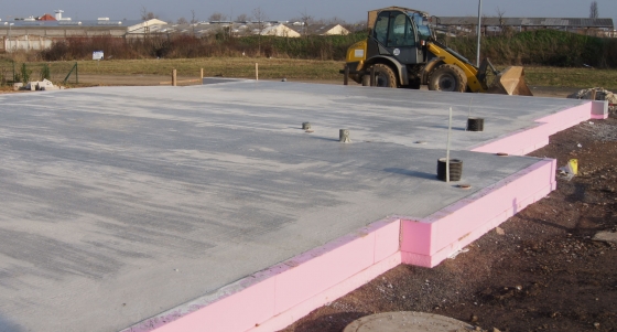
1.1 Bottom slab, foundation
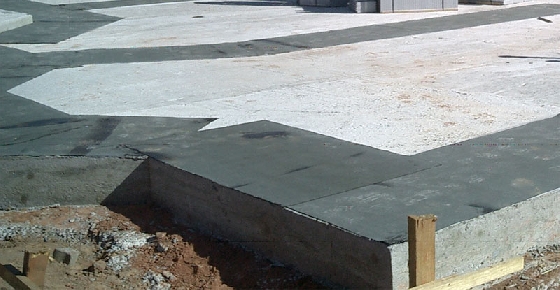
A well-levelled bottom slab/strip foundation is necessary for a smooth arrangement of the first elements.
Minor unevenness in the bottom slab (1-4 cm difference in level) may be levelled by underpinning wedges. Therefore, 3-4 layers of elements (in the height of 75-100 cm) need to be stacked, so that a levelling instrument can detect the highest point. To achieve an equal height, the lower areas need to be equalised by wedges. The wedges should be positioned in a distance of approx. 1,00 m, and the gaps (hollows) are to be filled with fitting foam glue.
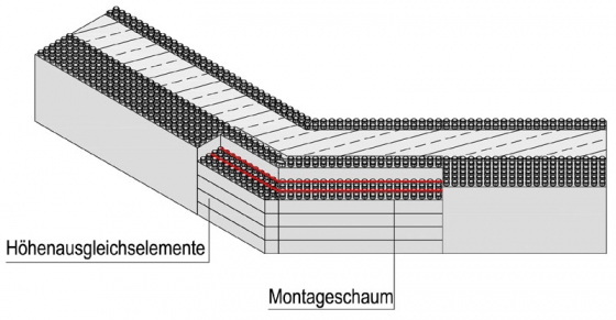
Major unevenness of the bottom slab (4-10 cm height differences), which usually do not occur during decent construction, are to be levelled with underpinning height compensation elements and chamfering of elements. In this case, attention should be paid to have an already concreted 1st element-row (10 cm), in case of noncompliance, the elements are going to pull apart. (If minor unevenness appears, it is recommended to order an ARGISOL instructor for supporting help.)

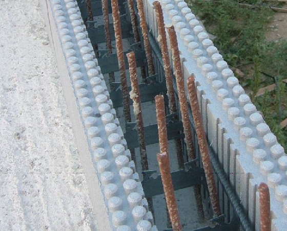
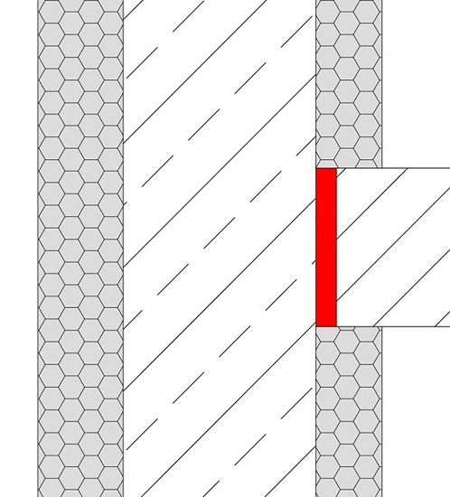
1.3 Starter bars
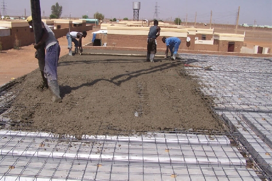
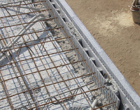
If torques or thrust (e.g. due to earth pressure) have to get absorbed, the connective reinforcement given by the stress analyst has to be laid before concreting the bottom slab.
The steel rods should be concreted in a certain way in the bottom slab, so that they are located between both heat-insulating slabs of the ARGISOL-elements without touching them (concrete cover). (See static calculation)
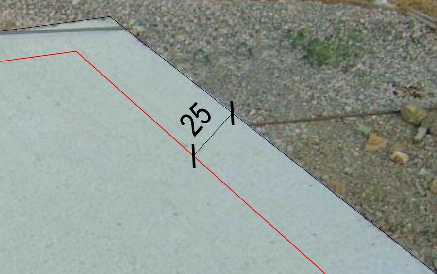
Measured from the effective outer edge of the wall,
If 35cm wall: min. 18 cm, max. 27 cm
If 25cm wall: min. 9 cm, max. 17 cm
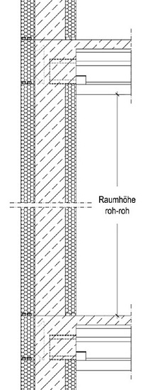
1.5 Height of room
Before arranging the first layer, the final height of ceiling (dimension in unfinished state) has to be reckoned exactly, because it may be decreased up to 5cm by cutting the bottom side of the element.
1. Example:
Ceiling height dimension in unfinished state = 2,46 m
Execution:
10 layers ARGISOL-elements, whereof 1 layer is reduced by 4cm.
Total: 9 x 25 cm + 21 cm = 246 cm
When cutting the elements by circular saw, there needs to be paid attention for the metal inserts not to get into the saw blade, because that could damage the saw blade. Alternatively the elements can be cut by a handsaw.
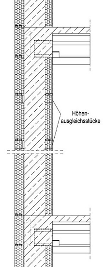
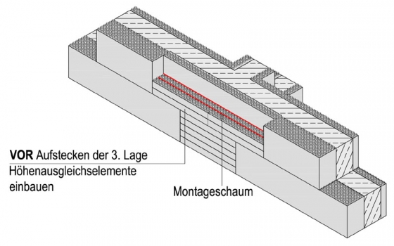
If the requested dimension in unfinished state cannot be achieved by cutting the 1st layer, it is recommended to use height compensation elements, which permit a partition of 5 cm stages.
It has to be paid attention, that the height compensation elements must not be stacked on top of each other! In such case the high concrete pressure could press them out. It is recommended to use the height compensation elements between the upper element layers.
2. Example:
Ceiling height dimension in unfinished state = 2,60 m
Execution:
10 layers of ARGISOL-elements, after the 8th and 9th layer a height compensation element each.
Total: 10 x 25 cm + 2 x 5 cm = 260 cm
3. Example:
Ceiling height dimension in unfinished state = 2,625 m
Execution:
10 layers of ARGISOL-elements, whereof the first layer is reduced by 2,5cm, after the 7th, 8th and 9th layer a height compensation element each
Total: 9 x 25 cm + 3 x 5 cm = 262,5 cm
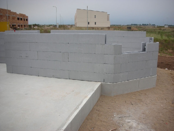
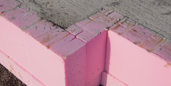
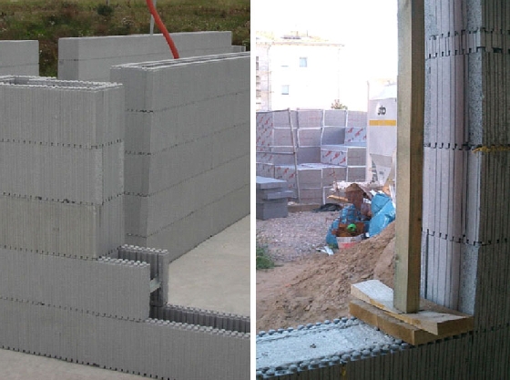
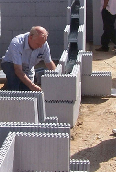
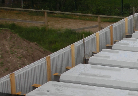
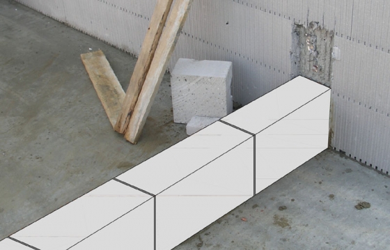
1.6 Setting the first layer
Beginning by corners, set the ARGISOL-elements up on the bottom slab. The thicker heat insulation of the norm elements has to face the outside. The thinner heat insulation slab of internal corners (25 cm wall system) of all corner elements faces the outside.
In case an insulation is intended to be a protection against moisture, apply it on the bottom slab before the first layer of ARGISOL. The most suitable product for that, is a cement based sealing compound or bitumen waterproofing insulation. There also can be used foils of plastic or bituminised felt.

1.7 Cutting the elements
If necessary, the elements can get cut for part measurements. For this purpose use a fine bladed handsaw (styrofoam saw) or a hot wire cutter. Waste material can be reused without difficulty. Due to structural reasons, part elements with less than 3 metal inserts can be used in the upper layers only.
Never use parts without metal inserts!


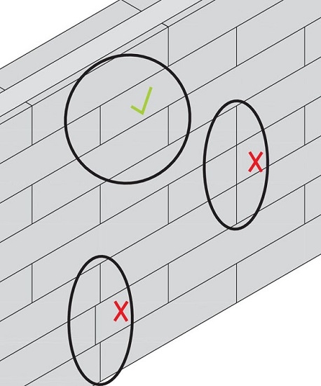
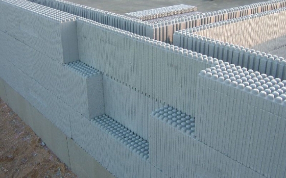
1.11 Masonry bond
Beginning with the wall corners, stick the further layers. By alternate use of the left and right corner elements, a bond of 25cm is going to develop (corner bond).
While sticking the elements, ensure, that there are no cut kerfs directly above, or too close to each other. (masonry bond!)
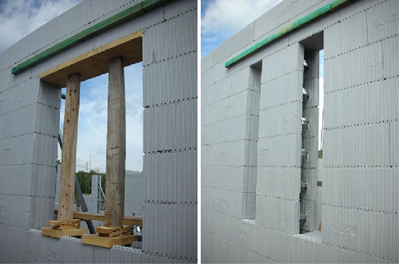
1.12 Lintels


If complete lintels are provided, determine the length of lintel elements as follows: width of the clear opening plus two times the support width. For supporting, 7,5 to 12,5 cm is sufficient (3-5 nubs).
To achieve the desired length of the lintel elements, connect the front-sided shaped dovetails. To obtain part dimension, always cut the side with the projecting dovetail.
The achieved rest piece reusable. Just insert it next to another lintel element.
If the length of the delivered ARGISOL element conforms exactly to the required ones, just cut off the overlapping dovetails.
Cut the bottom of the lintel elements up to the reveal insulation in the area of the supports, so that the lintel elements do not lie on the rigid foam.
Place the lintel element on both bearing areas.
Encase the lintel element with boards and screw clamps, so that it won’t get pulled apart when filling in the concrete.
For each side, there also can be used a roof lath that is clamped with tying wire through the lintel.
Important:
Absorb the weight of the concrete by supporting the lintel. Alternatively to timber formwork, ARGISOL elements can be used for support, too.
The required reinforcement of lintel elements varies, depending on load and span.
For calculation take the net section of 13,3 cm width and a height of 19cm.
Also consider the slab thickness relating to the effective depth.
If the full effective depth of 19 cm is static not necessary, polystyrene boards can get put into the lintel. The polystyrene boards must get stuck together underneath of each other. After placing the concrete, the polystyrene can get removed. Advantage: higher headroom of doors and higher windows, without changing the grid dimension of 25 cm.

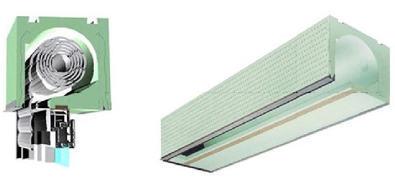
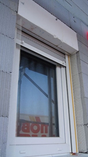
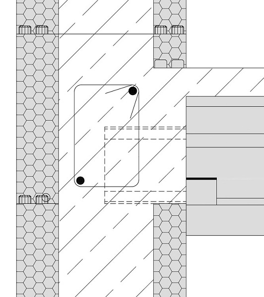
1.13 Roller shutter casing
Complete roller shutting casings of a width of 25 cm and respectively 35 cm, as offered by different producers, can get integrated into the system smoothly.
In the window areas the ceiling of the execution without lintels takes the static function of the lintel and has to be correspondingly reinforced. Well-suited is the use of window elements with integrated roller shutter casings.
In case of using windows with build shutter elements, care has to be taken, that the distance of the roller shutter casing with the roller guide rails is built in with a distance of 10 cm from exterior edge of the exterior of the ARGISOL element. At time of plastering the exterior walls, in front of the roller unit single boards or height compensation elements can get inserted into the lintel ground, but here also can polystyrene boards get glued in the place (see photo). Therefore, an optical frame with the same width on the sides and on top of the window is visible, and the high build shutter unit is covered and additionally insulated.
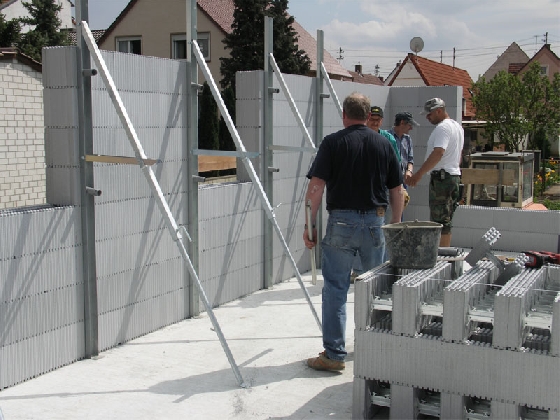
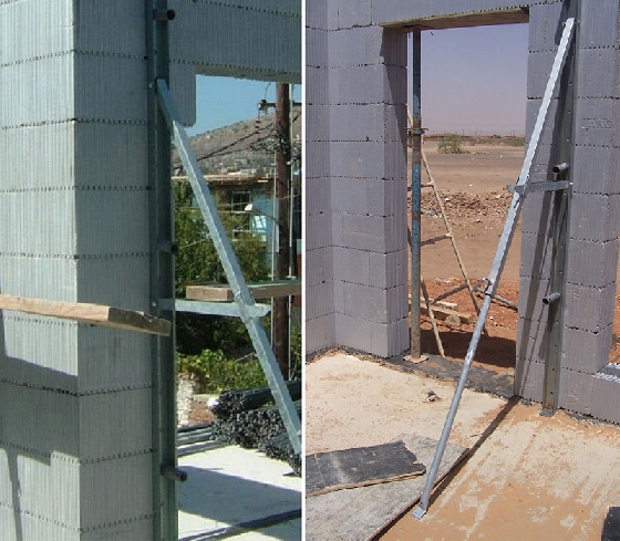
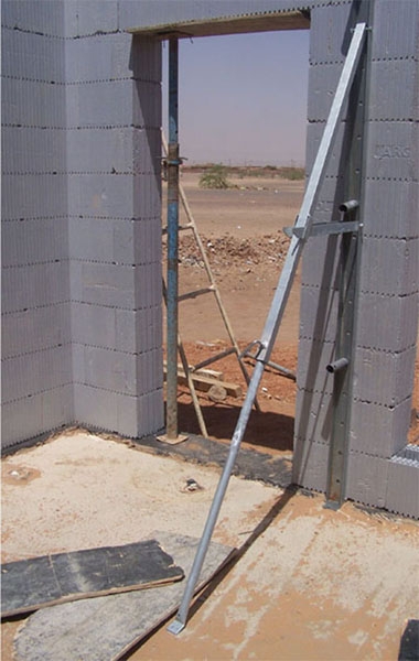
1.14 Retaining of the wall
For exact alignment of the ARGISOL formwork elements, it is recommended to additionally strut the wall. For this purpose, it is recommended to use especially for this building technique developed ARGISOL-push-pull props. This tool is the most perfect and simplest way of supporting and aligning the wall elements.
The push-pull props must be fixed at an early stage, to be stable enough even in severe wind.
Allocate the push-pull props in such a way, that they stand on both sides of openings and pillars about every 1,2 m to 1,5 m.
The delivered corkscrews (anchor screws) are to be screwed through the holes in the profile board of the push-pull props into the polystyrene.
When concreting one storey in one flow, 4 anchor screws per push-pull prop are necessary, of which one is to be situated approx. in the middle, one in the lower and two in the upper push-pull prop (e.g. 2nd, 5th, 8th, and 10th layer).
The push-pull props should get connected over the whole height of wall of the ARGISOL elements and get fixed directly to the bottom-/ceiling slab. Pull out the reporting strives into desired length und fix them to the bottom-/ceiling slab as well.
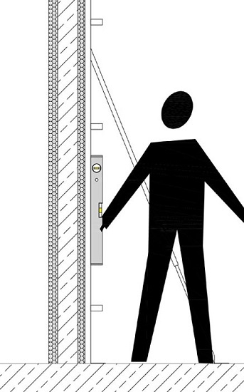
Plumb the push-pull props by means of a plummet or water level. Fix them in their correct position by clamping of the clamp lever on the reporting strives. Using this, the ARGISOL-wall is aligned.

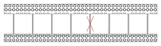
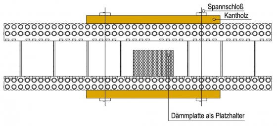
1.15 Extra formwork
At some execution it can happen that an additional formwork is necessary.
Example:
A waste pipe is placed, and the metal bars of the elements are blockading the way. So when the metal bars get removed, there is a lack of extra formwork in this area, and the element would fracture during the concreting. For this reason, it is important to secure the inner- and outer shell of the ARGISOL-element with a wood formwork and tightener or binding wire.
1.16 Pouring in of the concrete
For filling, concrete type C25/30 XC4 XF1 XA1 F3 8 (in former times B25/08 KR) should be used according to specifications of DIBT. The consistency should vary between kneadable and pliant; in normal case use norm consistency. For achieving a good water-/concrete factor, it is recommended to adjust the consistency by plasticiser and not by adding water. When ordering concrete, necessarily specify F3 pasty or F2, and if F3 is delivered fluid, do not accept it. The elements could rupture during concreting and get damaged.
According to static requirements, the stress-analyst can choose a different concrete quality.
If ARGISOL height compensation elements are used, the outer heat insulation should get covered up before concreting, with the object of keeping it clean. For this use either a wide adhesive or special cover fillets out of plastic.
A concrete funnel is used for filling by crane. It is kept between both heat insulation slabs, so that the concrete is filled targeted without any loss into the inner of the ARGISOL wall.
The concrete is filled into the formwork elements very economically by applying with a variable ruck-mounted concrete pump with an end hose of 60mm.
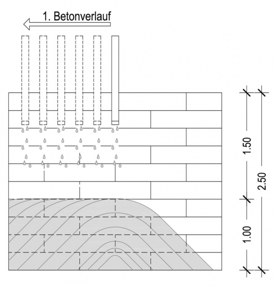
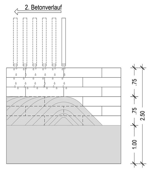
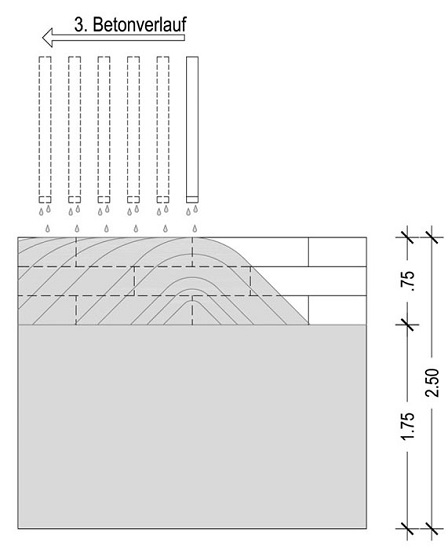
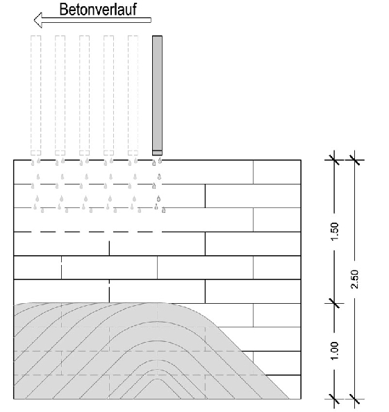
The ARGISOL wall is filled storey-high in about 3 applications. Be sure that several concrete processes with max. 1,00 m, beginning with the middle of the wall takes place.


Example:
Wall height = 2,50 m
1.Concreting process 1,00m
2.+3. Concreting process respectively 0,75m
Wall height = 2,75m
1+2 Concreting process respectively 1,00m
3. Concreting process 0,75m
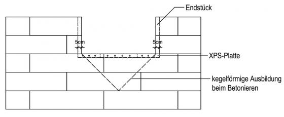
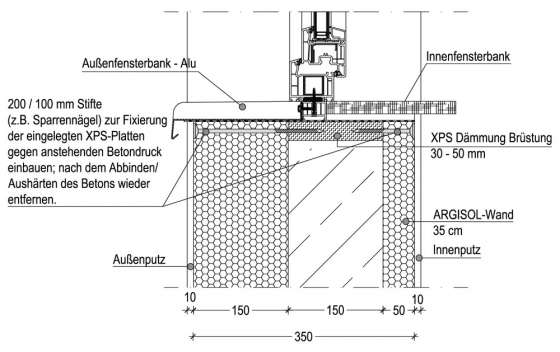
Under no circumstances, fill the windowsills at the first concreting process! If the concrete consistency is right, a V-formed hole develops at the windowsills, which gets filled during the last concreting process.
If the windowsills get completely filled during the first concreting process, the filled windowsill is going to flow over during the second and third process.
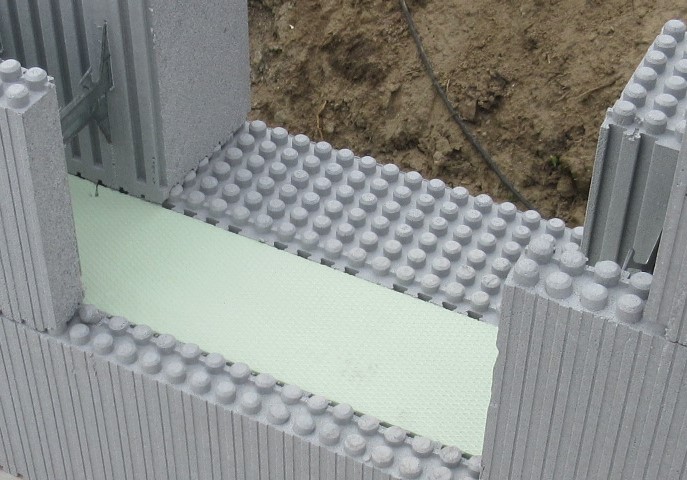
Before filling with concrete in the area of the windowsill, polystyrene boards, which are respectively 5cm wider than the window opening, are to be installed as a heat insulation.
Leave a 30-50cm (according to window width) as a sight opening for controlling the concrete while filling it in.
After the complete concreting process of the windowsill the sight opening has to get filled with polystyrene boards as well.
The insulation boards get fixed against increasing concrete pressure by 200/100 mm dowels (for example rafter nails).
After hardening of the concrete the dowels can get removed.
1.17 Compacting of concrete
By fall velocity, dead weight and the good slipperiness of plastic concrete, it partly compacts itself. But basically concretes should get compacted by according to DIN suitable aids (for example vibrator).
In strongly reinforced sections it may occur that concrete compacts only with effort by pocking or tapping. The use of a vibrator of a small diameter is helpful here as well.
1.18 Concluding works
Important:
The walls have to get checked immediately after concreting for true alignment and plumb, and if necessary get readjusted. Also control all box outs (sockets, gearbox of roller jalousie etc.) for position. Corrections are possible until the concrete hardens.
Push-pull props and as anchor spirals as well as dirty wall surfaces can be cleaned by water.
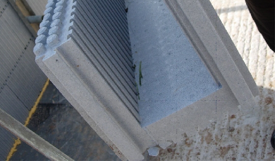
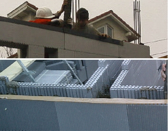
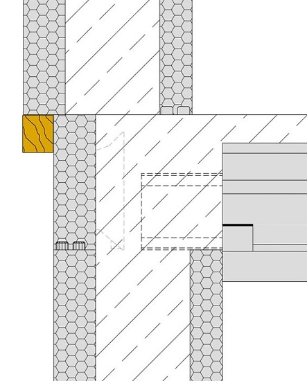
1.19 End element of the ceiling
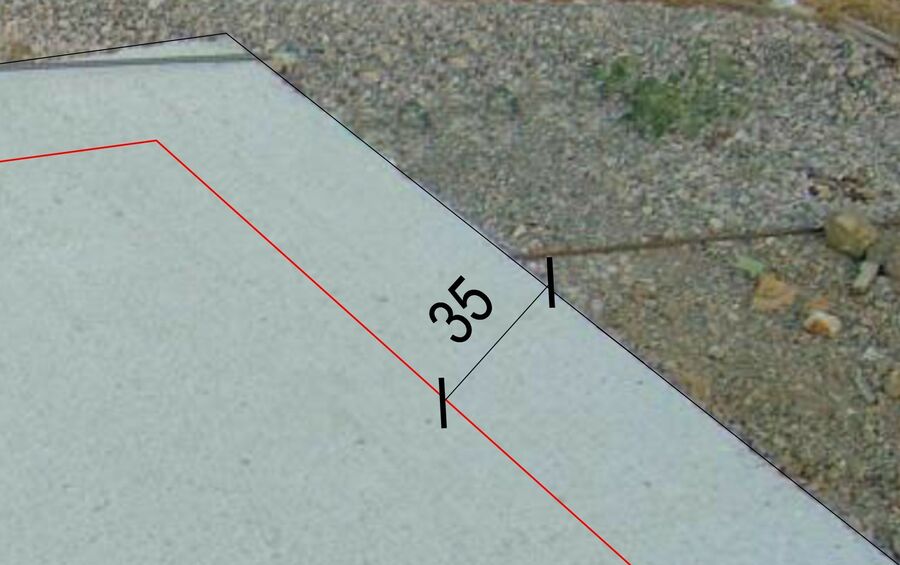
After concreting and checking the plumb of the recently concreted walls, the end element for ceilings has to get stacked immediately to the exterior heat insulation board, and 30cm long reinforcing steel rods (rest pieces) are to be inserted through a camber inside the recent concrete in distance of 35cm to each other.
Mitre the end element for ceiling at the corners. For this, follow the grooves on the upper side and on the lateral surfaces using a saw.
Fill in the chambers of the end profile for ceilings with liquid concrete and ensure they are truly aligned.
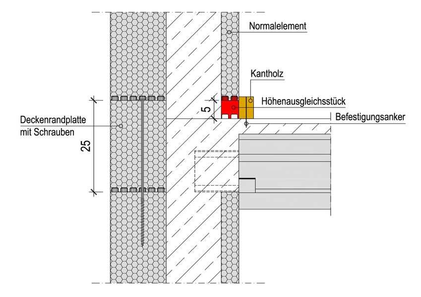
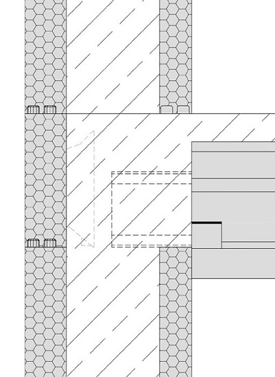
Alternatively ceiling edge boards with woods may be used, which are to be slid in before concreting the walls. 3 woods per end elements for ceilings (1 m long) are to be used for stabilisation. Cut ceiling edge boards of less than 60 cm length require 2 woods. For a 35s ARGISOL-Wall only ceiling edge boards with woods can get installed because of production related reasons.
While using ceiling edge boards it must be considered that the element has a height of 25 cm, but the ARGISOL ceiling only has a height of 20 cm. The ceiling edge board so protrudes the ceiling for 5 cm. When setting the next row of elements, height compensation elements have to get installed on the inside under the first layer. These elements have to get assured with a at least 5-6 cm high square timber, what means the square timber gets fixed/dowelled along the height compensation elements on the concrete ceiling so that they can’t rupture when later concreting the walls.
You can follow the course of action also, like with a bottom slab with big unevenness: the first row of elements gets concreted for 10 cm beforehand. This technique is a big effort, because only the inner side needs to get compensated.
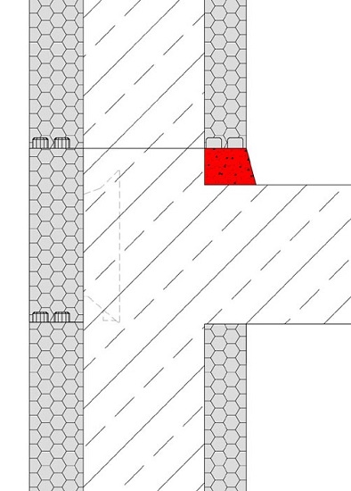
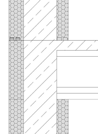
1.21 Thickness of ceiling
f, after concreting, another floor is added with ARGISOL, depending on thickness of ceiling, it may be necessary to apply a levelling course of cement mortar, or to fill in the air gap after alternating the ARGISOL- elements with fitting foam glue. The difference between height of ceiling edge board (20cm) and the chosen thickness of ceiling is the required height of compensation layer.
It is also possible to cut the overlapping part of the end element for ceilings levelling to the top edge of the ceiling, using a saw. The further works effect as already described.
Having a ceiling strength with more than 20 cm (e.g. hollow concrete floors), ceiling edge boards with woods should be used.
1.23 Separation layer
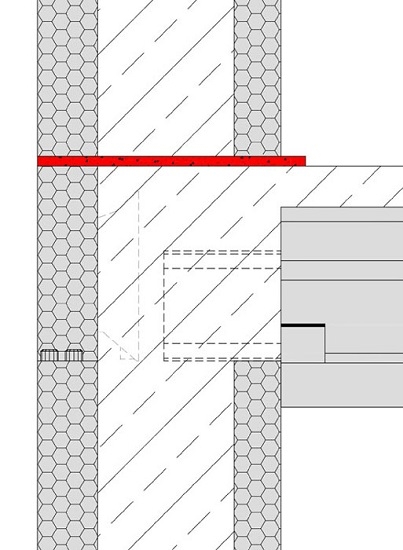
In case of high demands for acoustic insulation by the building, a separation layer out of rubber or agglomerated cork (e.g. ISOLGOMMA, PRONOUVO etc.) is recommended. By forceful separation of all contact points, the sound transmission to other rooms is reduced considerably..
Lay the rubber- and cork stripes below all bearing inner and outer walls to avoid differences in compression settlements. Please make sure no mortar bridges affect the efficiency of the procedure.
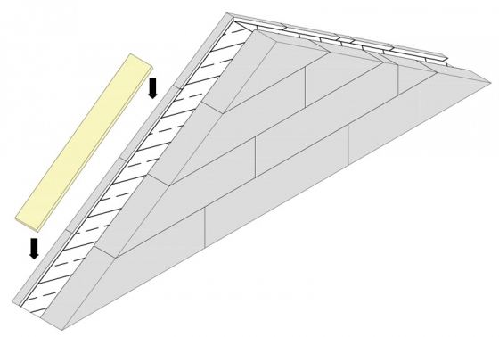
1.24 Gable walls
For building pitches of the roof, stack ARGISOL-elements to just below the intended height, and stack the last layer (slope of gable) with ARGISOL-gable elements. As there are end elements on the slope of gable now, they can get cut smoothly by using a handsaw to the required slope. The end elements also have the advantage, that outflow of the concrete is prevented while filling it in. Basically, the concrete should not be in a liquid consistence for filling in the upper area of gable walls.
Slope of ceilings: 26°-75°
According to the plan of a house, starter bars should be allotted for gable walls that stand separate (do not have a bonding to ARGISOL-inner walls). This constructive provision, which mostly is not listed in the structural analysis, is a preventive protection against wind pressure and other forces.
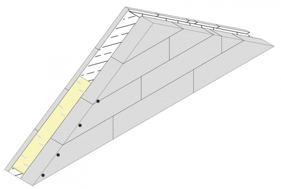
After concreting immediately install heat insulation boards (thickness 4-5cm) and fix against upcoming pressure of concrete with 22/100mm dowels (e.g. rafter nails). After setting/hardening of the concrete the dowels get removed.
ATTENTION!
For firewalls, the end pieces in the gables have to get removed and to get encased, so that a shut concrete core without interruption of foam material develops. The isolating course of the upper slope has to get filled with mineral rock wool (e.g. Knauf) for fire protection- and sound regulations.
1.25 Installation of conduits
By cutting out a small stripe (pipe slot) by means of a hot wire cutter, laying of pipes inside interior heat insulation after concreting is possible. If requested, incorporate pipes with PU-fitting foam glue. After hardening, cut the overlapping parts of foam material flush with wall.
For better sound insulation, nowadays usually drainpipes with front wall-installations are carried out. Fall pipes are laid on the interior side of the exterior walls and subsequently faced with gypsum plasterboard.
Furthermore, there is a possibility to lay the drainpipes subsequently inside of the ARGISOL-walls. For that purpose, insert an end element behind the interior heat insulation board before concreting. Slits can get created without completely interrupting the concrete core. After setting time of the concrete the insulation and the end piece gets cut off. Set the drainpipe in the resulting cavity.
Desweiteren besteht die Möglichkeit, die Abflussrohre nachträglich in die ARGISOL-Wände zu verlegen. Dazu wird vor dem Betonieren ein Endstück hinter die innere Wärmedämmplatte eingeschoben. Es können Schlitze hergestellt werden, ohne dass der Betonkern ganz unterbrochen wird. Nach der Abbindezeit des Betons werden die Dämmung und das Endstück herausgeschnitten. In dieser Aussparung wird die Fallleitung verlegt.
The installation of pipes into the concrete core should be avoided because of sound- and fire protection regulations.
Bigger cavities like e.g. pipe ducts or intended disruptions in the concrete core are possible by simply slipping in end pieces. Before the installation of pipes into the concrete core, ask for agreement of the stress analyst.


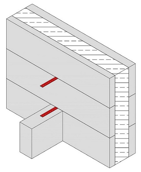
1.26 Connection of the inner walls
There are two possibilities for the bond of non-bearing interior walls:
Bonding with perforated metal tape or bonding by cutting off interior insulation.
Remove two nubs of the inner shell in the area of the subsequent bonding of the non-bearing wall. Depending on the strength of the perforated metal tape cut in the interior insulation additionally. Bend the perforated metal tape with a metal insert by means of a wire, to avoid slipping while concreting. Repeat process in every layer.
After completion of the ARGISOL wall, the perforated metal tape need to get bended back on the exterior side of the inner insulation, and the non-bearing wall can get fixed by help of the perforated metal tapes.
Alternatively the area of connection up to concrete core gets detached, and gets run to the brickwork. Connect the interior wall with mortar holohedrally to the concrete core.

Bonding of bearing interior walls into the 25cm exterior walls is carried out with the ARGISOL-T-elements.
The installation of bearing interior walls into the 35cm exterior walls is carried out with the ARGISOL-T-elements (25cm). Fill in the discontinuities between 25 T-elements and 35 wall system with height compensation elements und fix lateral with fitting foam glue.

1.27 45°-angle elements
hese special elements for inner and outer corners of 45° (exterior angle) get put together alternating turns of left and right elements.
The installation of angle elements into the 35 cm exterior walls are to be done with the ARGISOL 45° angle elements (25cm). Fill in the discontinuities between 25 angle elements and 35 wall system with height compensation elements und fix lateral with fitting foam glue.

[Translate to Englisch:] 1.28 Eckrundelement
[Translate to Englisch:]
Beim Einsatz von Eckrundelementen ist für Winkel von 90° gleich vorzugehen wie bei Eckelementen.
Für beliebige Winkel die Gradeinteilung auf der Oberseite der Eckrundelemente beachten, welche den Außenwinkel angibt. An der gewünschten Stelle die Elemente trennen und den längeren Abschnitt zur Ausbildung des Winkels verwenden.
Danach durch abwechselndes Aufeinanderstecken der linken und rechten Eckrundelemente, diese mit den anschließenden Normalelementen im Verband aufstecken.
Es ist zu beachten, dass diese Ecken besonders gut abgestützt werden.

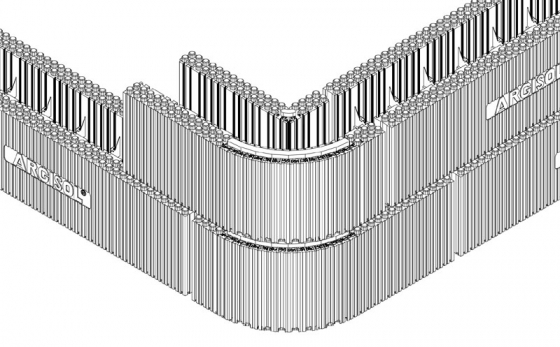
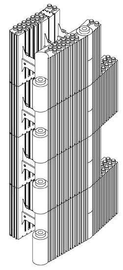
1.28 Rounded corner elements
By using rounded units, radii between 70 cm up to straight lines can get achieved.
Draw the intended roundness on the bottom slab and position the elements in such a way on it, that the opening at the side with the thinner heat insulation always shows the same gap.
Hold one of the delivered wedges on the gap and read the letters at the surface laying below the inner and outer edge. Cut the wedges exactly by saw, following the dovetails.
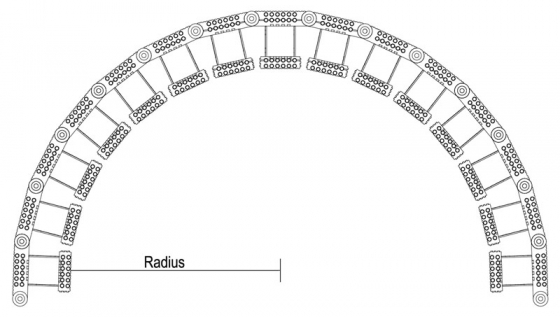
Slide the prepared wedges, with the label up, into the opening, and take account that the wedges have to get inserted into each single layer.
To achieve a bond with ARGISOL-norm elements, cut the hinges by turns, in change over straight line – arch in the second and seventh spacing groove of the thicker or in the first and sixth separation line oft he thinner heat insulation.
A bond of 12,5 cm will result.
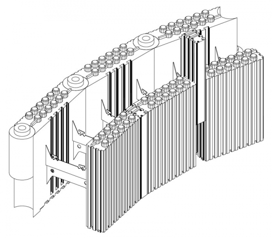
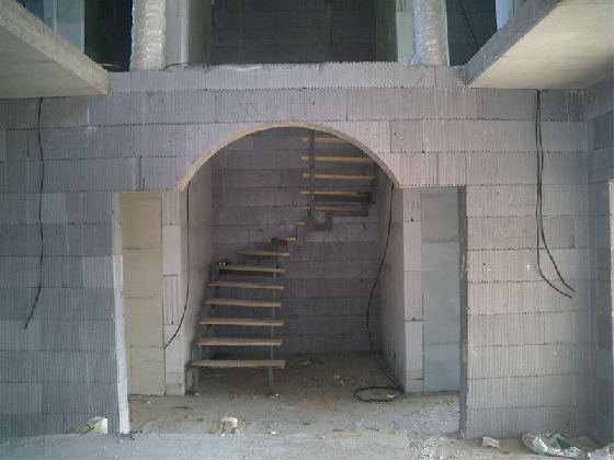
1.30 Round arch openings
Draw the round arch on the bottom slab, wooden panel etc. Connect ARGISOL couple of single boards with 6 end elements, to create an ARGISOL element with polystyrene inserts.
In the area of cutting-mark put single boards flat on the ground, use ARGISOL norm elements outside of the cutting-mark.
Stack all elements together, lay them flat on the ground and draw the cutting marks on both sides.

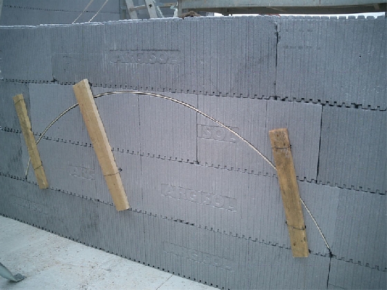
Cut precisely and cleanly along the cutting mark on both sides with a handsaw. Tension a wood fibre board (ca. 3-5mm thickness) on top of the cut arch and fix it with wire (turn the plane side of the fibreboard upwards).
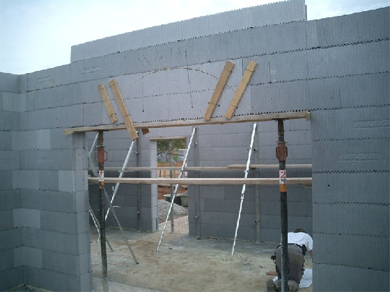
Put both parts together again, and fix them with roof laths/lumber rests. Install the prepared wall element in the provided wall opening now.
Brace it collaterally with woods and support it underneath. Remove casing and lower arch piece after concreting. Take setting time of concrete into account!
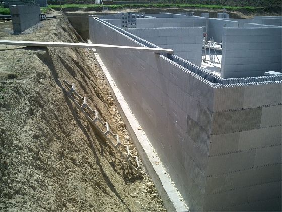
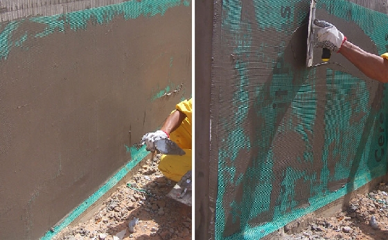
1.31 External cellar walls
Similar to conventional construction methods, humidity protection is required for ARGISOL cellar outside walls.
On the outer heat insulation, affixed foils (such as Köster, Deitermann, etc.) as well as solvent-free knifing filler offer sufficient protection.
Lead the humidity insulations by a chamfer to the drainage line.


[Translate to Englisch:] 1.32 Bewehren der Wände
1.32 Reinforcement of walls
For load bearing construction, only the concrete core gets taken into account. Its calculation is carried out to the norms of concrete- and reinforced concrete construction (DIN 1045). By variation of concrete quality and the reinforcement nearly all requirements of building above ground level can be reached.
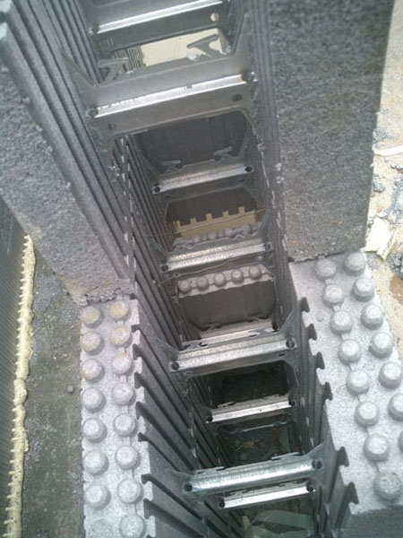
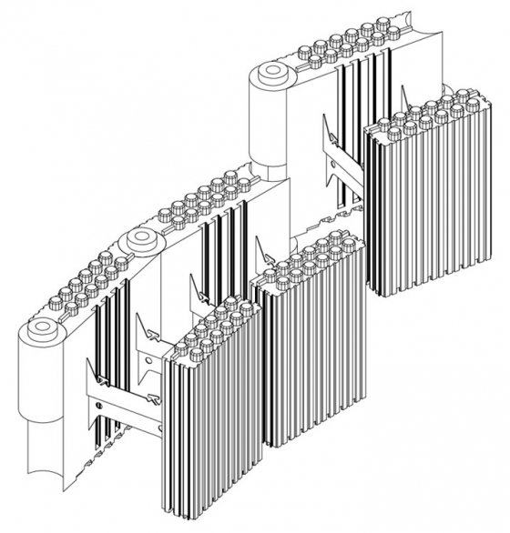
A reinforcement is only required, if bending moments are induced into the wall, or the buckling load for reinforced walls is exceeded. The in such cases by the stress analyst established reinforcement is very easy to set, thanks to the reinforcement holders on the metal fillets of the ARGISOL elements.
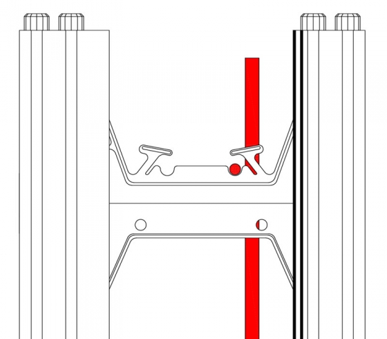

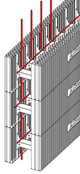
When alternating the ARGISOL elements, lay the provided horizontal reinforcing bars in every layer into the guide grooves and fix them in their position approx. every 50 cm by tilting or turning of the T-shaped holder.
By use of the inner guide grooves, e.g. in the 2., 4., 6., 8., and 10. layer, a vertical offset is reached. To fix the reinforcement bars, slip, after finishing of the wall, the vertical bars from the upper side between the staggered horizontal bars in. During the following concreting of the elements, the vertical reinforcement bars get pressed against the horizontal ones by the concrete, and so lay on the statically best place. The vertical laying metal bars prevent a collateral sliding.
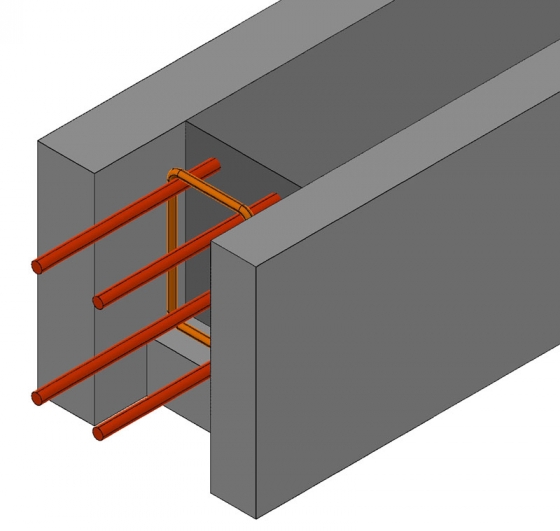
1.33 Wall ties
Two continuing reinforcement bars of at least 12 mm (ring beam) have to be positioned inside the interior-, and exterior walls, in each storey or cellar ceiling.
When using wooden beam- or hollow core ceilings, as well as when using jamb ceilings, a wall tie ring beam may be required.
It is imperative to consider the specifications by the static calculation regarding number and dimensions of the reinforcement.
1.34 Building sites in wintertime
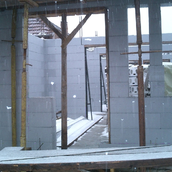
The hardening concrete creates heat, which is restrained by the heat insulation of the ARGISOL-elements, so that concreting in winter is possible.
If temperatures are below freezing point, make sure that the concrete does not freeze, as otherwise strength losses will occur.
Observe the following requirements:
- keep the water/concrete-factor as small as possible (concrete prolongation)
- choose the cement content as high as possible
- do not use frozen aggregates
- warm batched water or aggregates
- cover concrete
- add concrete additive
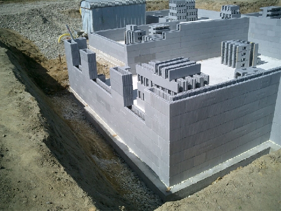
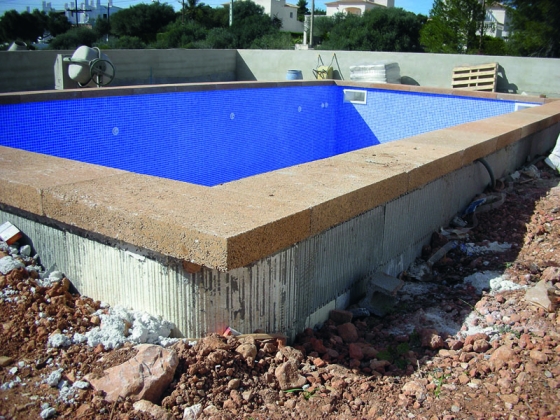
1.35 Swimming pool
The sun energy accumulated in water is not conducted to the ground thanks to the advantageous heat transition coefficient value of ARGISOL. For this reason, the system is perfect for constructions of swimming pools.
It hast to be considered to plan a connective reinforcement according to the size of pool stub bars in the foundation/bottom slabs for the ARGISOL elements when constructing swimming pools. After that, it is quite easy to install the required reinforcement into the walls, similar to the execution of cellar walls. Take quantity and dimensioning of reinforcement out of the static calculation.

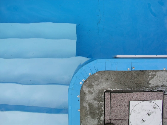
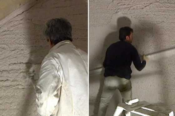
1.36 Moisture barrier
At high continuous humidity load, as, for example in indoor swimming halls, stables, trade- and industry buildings, in some cases a moisture barrier at the warm side of the wall is required as a protection against moisture penetration. Such a measure may also be required if dense linings (sintered clinker, ceramic coating, etc.) are applied on the cold side of the wall, restraining the emission of diffused moisture penetration. An object-related vapour diffusion calculation, which is done by architect or stress-analyst that is responsible for planning, shows whether a moisture barrier is necessary.
1.37 Damages
In case of damages to the inner heat insulation, foam the areas with fitting foam glue and cut overlapping material after hardening.
Cut away damages of the heat insulation on the outside in a rectangular way and fit a part of rigid foam (ARGISOL-waste) with polystyrene adhesive into the opening.
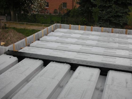
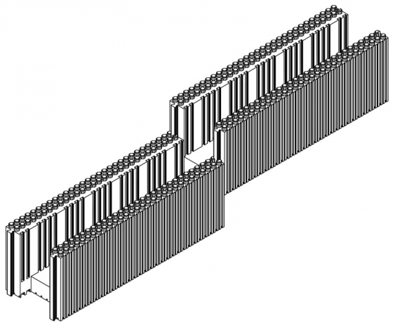
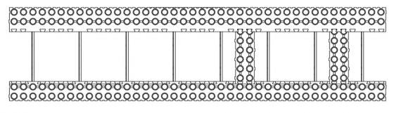
1.40 ARGISOL-ceiling
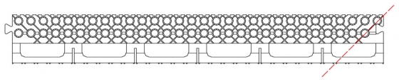
The ARGISOL-ceiling is classified under the technical term ribbed slab. According to client’s plans, it gets manufactured measured by 0,6-6,0m, to the exact cm.
The specifically, on demanded length made elements have a norm width of 60cm and are laid manually, starting at one side of the room.
The last ceiling element is cut calibrated lengthwise on the building site. Besides, sloped- or round cuts can get delivered as over length and get adapted to the walls on building site.
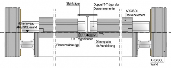
Bigger spans, over 6,0m, may be put into practise by means of steel girders.
The advantage is, that the plate girder of the ceiling elements is laid below the lower flange of the ceiling girder, and therefore the steel girder lays underneath of the ceiling level. The levelling of the wall in the steel girder’s bearing area has to get lowered for the girder’s flange thickness.